160 / 80 Meter Preamplifier
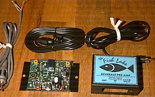
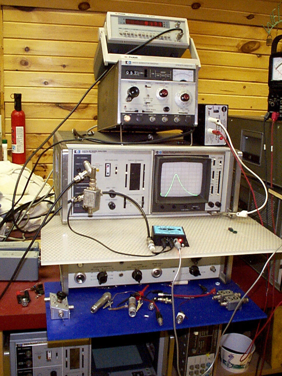
Shown above is the preamp and one of the test and measurement setups used during design and alignment.
FLP1
High-performance RX Antenna Preamplifier
Introducing a new accessory for the serious radio enthusiast and experimenter, the FLP1 brings state-of-the-art design and performance to everyone at an extremely affordable price. This device is designed and built by radio hams for radio hams, especially those who have an active interest in Dxing on 160 and 80M.
Most RX antennas for low-angle reception produce extremely attenuated feedline signals which must be amplified by 10-20db to match typical TX antenna signals (when used also for RX). Designing the necessary amplification is complicated by the simultaneous need for good intermodulation performance and rejection of strong in or near band interference.
To meet both of these needs, this preamp utilizes a state-of-the-art MMIC for the active amplification, preceded by high-Q bandpass filters. The MMIC is based upon GaAs technology and is able to produce 20db. of gain while maintaining an incredibly low-level of IM. This is specified in the form of a third-order-intercept point of +35dbm. This exceeds the IM performance of virtually all commercial ham radio transceivers.
This is the ‘intrinsic’ IM specification, which is the lower limiting value for very closely spaced in-band 3rd order components. Actual IP3 can be much higher for further spaced components as a result of the selectivity of the input filter. This is especially important for suppression of IM due to AM broadcast carriers mixing with signals on 160M.For these cases the effective IP3 may exceed 60dbm. The net result is an amplifier with plenty of gain to equalize the beverage signal with that of the TX (when used as RX antenna) without any of the degradation that frequently accompanies the use of high-gain devices at such low antenna signal levels.
The input preselector uses all passive, high-Q components to avoid any degradation of the inherently low-level of IM in the active electronics. It uses triple tuned circuits optimized to produce just enough bandwidth to cover the phone and CW DX bands without need for retuning. Electronic bandswitching between 80 and 160 is accomplished with a simple relay switching scheme. The 160M or 80M band is selected by grounding or ungrounding one conductor of the control cable. The other conductors are ground and +12VDC PS input line. A SPST switch is all that is required for 80/160 switching, and it can be located conveniently at the operating position. It can also be easily tied into more advanced station control systems which use band-decoding adapters.
Each band is provided with a trimmer capacitor which allows peaking the input filter to anywhere within the band. It is factory set at the specified frequencies and will normally not require any further attention. However, if desired the center frequencies can be changed by just removing the cover and adjusting the trimmer with a screwdriver. Input limiting is provided by a silicon diode clamp which prevents possible damage to the active electronics by high-level local fields. This clamp is operating well below the conduction ‘threshold’ to guarantee no IM generation which would impair its overall high-immunity from cross-modulation and in-band splatter by big signals. In practice, this circuit positively clamps with no damage at input signals which are 20db+ greater than would normally be picked up by long beverages in the fields of KW-carrying TX antennas. We have made measurements at a few typical stations to determine the level of input signals which get generated by beverages at high-power stations while transmitting, and found them to be well under the +40dbm limit guaranteed by these specifications.
The FLP1’s power supply line contains extensive RF and DC filtering to minimize problems with RFI from multiple transmitter stations as well as reverse battery protection in case of power supply miswiring. Generally speaking, we have attempted to make this accessory as bulletproof as practically possible.
It is feasible to directly cascade two units for very-high gain requirements. A cascaded pair will provide 40db (less filter loss) of power gain while maintaining all of its superior performance specifications. This extreme amount of gain is rarely needed but is readily available by this means.
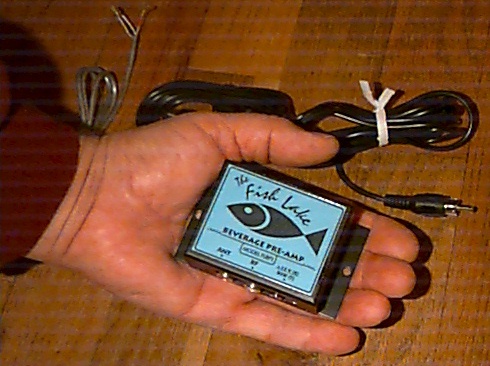
Construction of the FLBP1 is based upon contemporary technology using SMT components and two-sided PCB with ground plane. The final package is mounted in a custom metal enclosure which fully shields the electronics and provides a simple mounting flange for attaching to a flat surface (on a wall, back of bench, etc.) This results in a package which is very compact and ergonomic. It is intended to be placed somewhere in the station which is convenient for mounting and wiring and easily tucks away into unused spaces. There is virtually no need for operator access during normal operation.
Construction is not intended to provide full protection for outdoor usage. However, it can be easily sealed in a weatherproof container of modest size if that is desired. There are no requirements for cooling and the entire unit consumes less than 1W. of power even with the relay actuated.
It is supplied with a cable for the power supply/bandswitch. Two RCA phono cables not supplied.
Power Gain: 20db. nom.
Freq. Range: +0/-3db 1.8-1.95Mhz (160M)
3.50-3.8Mhz (80M)
Tuning Range: 300Khz (factory set at 1.85Mhz and 3.60Mhz)
Impedance: 50 Ohms In/Out
Maximum Input: +40dbm without damage
1db Compression: +15dbm INPUT
Noise Figure: 4db.
IP3: +35dbm
Selectivity: nom. 200Khz
Bandswitch: Mech. relay for 80M or 160M band
Switch Current: 10ma. (@12VDC nom.)
Power Supply Requirement: 12.0-18VDC @ 75ma.
EMC: Full I/O filtering and reverse battery protection
Size: 3 5/16”L (w/flange) x 2”D x 1”H
Weight: 4oz.
ANT Connector: RCA female jack
RX Connector: RCA female jack
POWER/CONTROL: 3.5mm Stereo jack - instructions included
3/25/08
| magic tricks |